 |
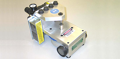
| The Zierick Mini Press |
| |
 |
 |
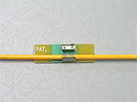 |
| The Zierick Surface Mount Insulation Piercing Crimp Terminal in pre-terminated condition. |
|
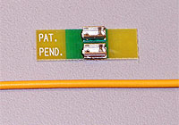
The Zierick Surface Mount Insulation Piercing Crimp Terminal in post-terminated condition. |
| |
 |
 |
 |
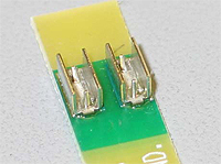
| Two SMT Insulation Piercing Crimp Terminals are shown soldered to the pads of a sample PCB, along with a typical 18 AWG wire (in the foreground). |
|
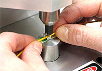
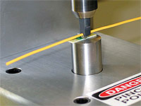
The sample PCB is loaded into the tooling of the Mini Press. The tooling comprises an upper die to form the “D” shape of the resulting crimp, and a lower spring-loaded anvil. The operator of the press places the wire loosely in the “U” shaped channel of the Terminal, then easily compresses the spring loaded anvil by pressing the PCB downwards, creating a gap between the die and anvil for placement of the PCB & wire under the die. |
| |
 |
 |
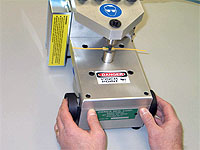 |
| The PCB & wire are now held in place by the spring force of the anvil against the die. The press operator does not need to hold the PCB or wire during the crimping cycle. |
|
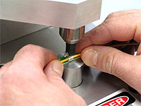
The press operator simultaneously depresses the two side-mounted actuator buttons to initiate a crimping cycle of the press. |
| |
 |
 |
 |
| The PCB & terminated wire remain held by the spring force of the anvil after completion of the crimp cycle, awaiting removal by the press operator. To remove the PCB & terminated wire the press operator simply presses downwards on the PCB to compress the spring loaded anvil, then slides the PCB & terminated wire out from under the upper die. |
|
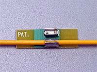
A close-up view of the PCB & terminated wire after removal from the press. |
| |
 |
 |
 |
| ZIERICK’s new Surface Mount Insulation Piercing Crimp Terminal shown next to traditional soldered wire terminations. |
|
Typical use of ZIERICK SMT Insulation Piercing Crimp Terminals for daisy chain connection of multiple PCBs in series. |
| |


 Surface Mount


