Please be patient as the movie loads. (It's worth it!)
This time lapse movie demonstrates the Zierick Header's forgiving tolerances and its ability to center itself on surface mount solder pads.
We began by placing a double row header and a single row header off the center of its corresponding pads. As the board is heated, the solder begins to melt. First the single row header will begin to move into place. As the capillary action draws the solder, it pulls the header assembly tightly to the PCB. Then the larger double row header will move into place. Notice how the solder wicks up the cavities as the board heats.
The pin is soldered into the plated through hole at the same time the header is soldered to the PC board.
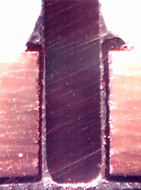
The capillary action provided by the four cavities (formed between the pin and plated through hole) will pull up the melted solder, resulting in a stronger solder joint.
The melted solder rises through the cavities and forms a ring at the top. The ring indicates that the reflow process is complete.
The force which pulls the melted solder into the cavities will also pull the header board assembly and the PCB together.
Ziericks unique header assembly features capillary action to improve solder joint strength. As a result, pin retention force is 50% higher than that of J-Lead type headers. As the capillary action draws the solder, it pulls the header assembly tightly to the PCB. At the same time, co-planarity problems are eliminated because the force generated by the capillary action also pulls the header into proper position over the solder pad even if the part has been placed off-center.
A circular solder pad on top of the board and a square solder pad on the bottom are connected to the conductive wall of the plated through hole. The size of the hole is such that it holds the square pin in place, yet leaves four cavities defined by the flat side of the pin and the curved wall of the hole. The cavities promote capillary action by drawing most of the melted solder up through the cavities where it forms a ring at the top side of the header assembly board. This solder ring is a visual indication that the reflow process is perfect and complete.
Further, because the header base is made of the same material as the PCB, there are no thermally induced stresses on the solder joint long term reliability is guaranteed. In addition, deep score lines run across both sides of the header base. The assembly is very flexible and can accommodate board warpage without weakening connections.
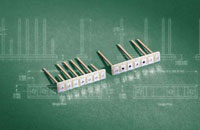
To meet varying application requirements, Zierick headers are available with pins missing at specified positions or with pins of different lengths and sizes. Pins are offered in brass or copper, and optional configurations are available.


 Surface Mount